Discussing the project with Furuno
Regina Laska is treated like a professional deep sea vessel
![]()
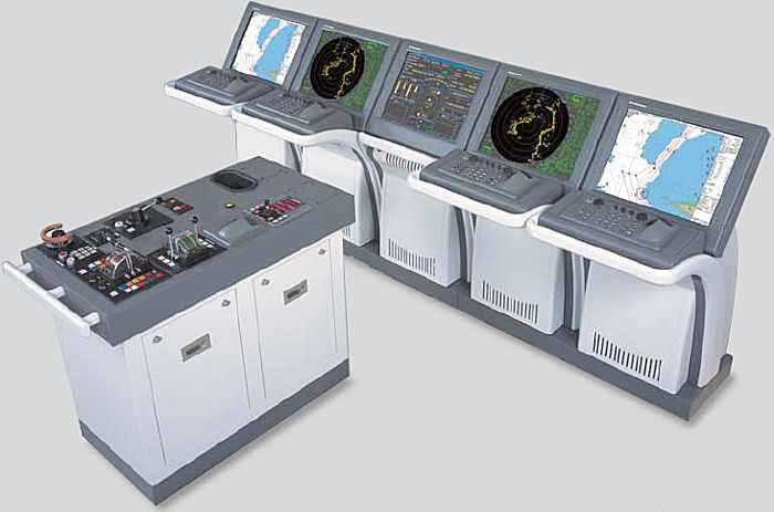
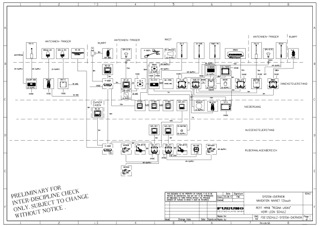
The Furuno Voyager, Integrated Bridge System (IBS) for deep sea shipping
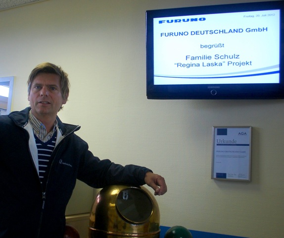
Furuno gave us a big welcome to Hamburg.
Photo by Jessica
Ever since we have been working with the professional deep sea shipping industry, I have had great respect for Furuno’s professionalism and customer relationship. This time, however, I would experience Furuno from a different angle: For the first time, I would not just write about them as an editor, but I would become a customer myself.
Furuno is one of the few suppliers who are not only dealing with the marine leisure industry but who are, at the same time, deeply involved in the professional industry: fishing vessels, work-boats, ferries and deep sea shipping. These customers have a very high demand on their suppliers and their products regarding reliability, serviceability, engineering, project management and after-sales service. Furuno’s approach and their history in serving the professional industry is said to spill over to the yacht segment as well, which makes not only their products, but also their engineering services, highly attractive to me.
Would they be able to fulfill our high expectations?
Hamburg-based Furuno Deutschland takes engineering one step further and offers a similar technical support to a yacht as they would give to a professional deep sea ship-owner. The onboard electronic systems are discussed in close co-operation with the owner in order to build a navigation network that exactly fulfills the requirements of the customer.
The documentation that is delivered together with the equipment is exemplary. The clear and easy-to-follow charts are invaluable for the installing engineers and are worth their paperweight in gold when it comes to trouble-shooting many years later, in case somethings goes wrong or if you wish to add more instruments or equipment. Each cable is clearly marked on the charts and can easily be identified and tracked on the boat.
Even if this documentation does not come cheap, I believe you save at least the same amount of money thanks to a quicker installation and a more precise repair in the years to follow.
 Furuno’s approach was exactly what we wanted and that was the reason why we traveled to Hamburg to meet with Furuno Deutschland GmbH.
At 13.00 on a Friday afternoon we stepped into the headquarters of Furuno Germany, where we were given a big welcome by its staff. Everyone seemed to know that we were coming and gave us a feeling that we were guests of honour. A TV screen was displaying: “Furuno Deutschland GmbH welcomes the Schulz family and the Regina Laska project“.
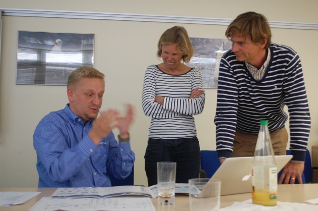
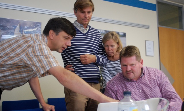
We were lead to their conference room where three people would spend the full day with us: Frank Westphal from the Engineering&Projects department, Rüdiger Engel, General Sales Manager, and Claus Frederiksen, Managing Director of Furuno Deutschland.
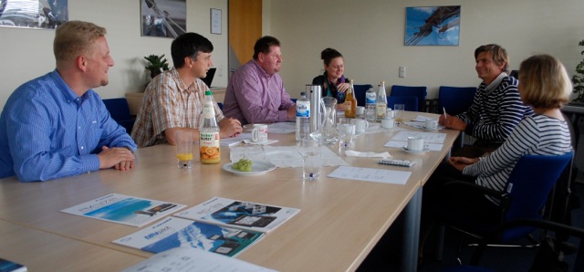
From left to right: Frank Westphal (Engineering&Projects) Rüdiger Engel (General Sales Manager), Claus Frederiksen (Managing Director), Melanie Meinen (Marketing), Leon and Karolina. Photo by Jessica
The team from Furuno was very well prepared and showed a sincere understanding for our needs and intentions with the boat. It became a very fruitful discussion whereby not all our crazy ideas were accepted right away. Their profound engineering know-how and experience gave us very valuable inputs and suggestions how to choose our navigation and communication system.
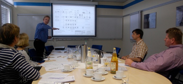
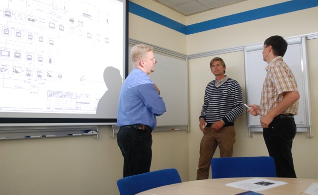
Frank Westphal explains the proposed system overview of Regina Laska. Photo by Jessica
 Furuno had already prepared a proposed system overview including all suggested components as well as their interconnections. It took the entire afternoon to go through each individual instrument and discuss how they communicate via the Ethernet-network, the NMEA183 and NMEA2000. Why so many network systems? Simply because of redundancy. Essential navigation equipment must still work if, for instance, the Ethernet would break down due to the unlikely event of a hub failure.
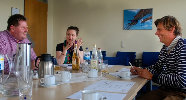
In addition to having a business relationship, Claus has been a very good friend to us for many, many years. Photo by Jessica
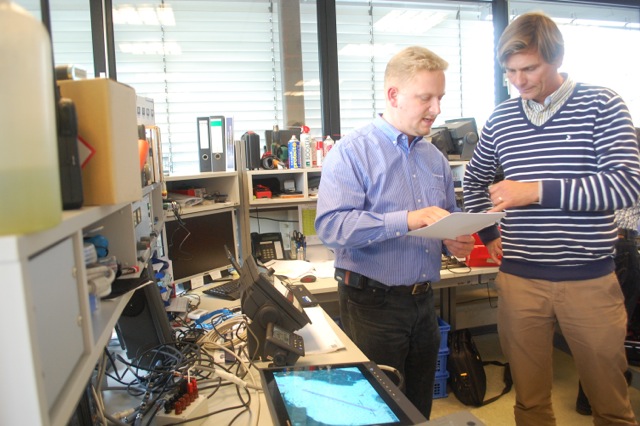
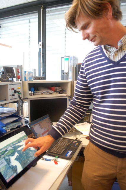
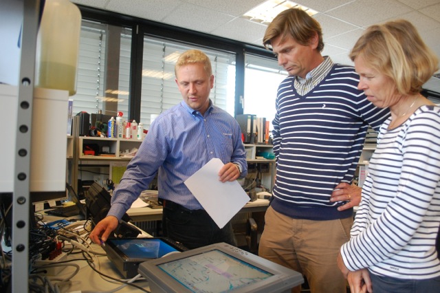
When we needed to decide on various alternatives, we went down to their lab where they had prepared some equipment for us so we could try them out and see how they work with each other. Especially cool was when we could use our own iPad to monitor the entire ship’s data available on the network.
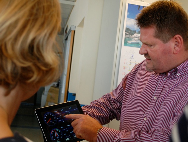
Claus Frederiksen demonstrates how he can monitor the ship via his iPad. Photo by Jessica
We talked and discussed until we finally all happily agreed on a system we found being the optimal solution.
Overall concept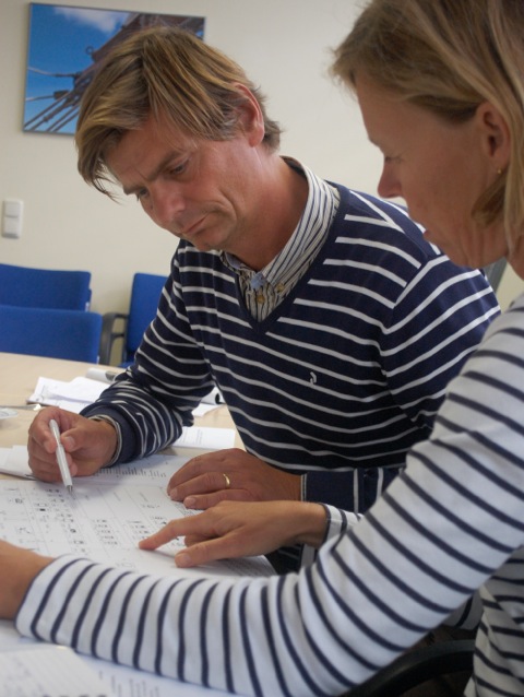
The overall concept of Regina Laska is robustness, understandability and redundancy.
Robustness results from Furuno’s background as a supplier to fishing vessels and work-boats.
Secondly, robustness is also a question of where and how the components in question are being installed. For instance, we spent a lot of time discussing the placements of the individual antennas so they do not take harm from or interfere with each other.
Understandability is a very important request from our side. First of all, I want a clear understanding of how the individual systems work together and which electronic box is connected to which and with what cable. A good portion of Germanic “Ordnung” is what is needed when so many electronic devices are interconnected. Today’s communication and navigation systems all work together and therefore documentation is becoming more and more important for a successful installation.
Further to the installation as such, I wish the crew to easily understand the systems. It should be intuitive to use and control the navigation and communication systems onboard.
Redundancy is a way of thinking rather than buying everything in couples. You don’t need two of everything but you need to be able to solve the same problem in two different ways using independent pieces of equipment. Therefore, “what-if-scenarios” were intensively discussed during our meeting with Furuno. We wouldn’t give up until we had an answer, knowing exactly which other components would take over and solve the same problem and act as a work-around until the device in question has been repaired or replaced.
Another important factor that reduces vulnerability is to make sure that essential equipment works independent of the network, meaning that if one one piece of equipment malfunctions, the rest should still function independently.
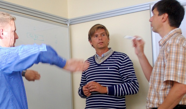
Frank Westphal can’t hide his eagerness when explaining the importance of redundancy. Photo by Jessica
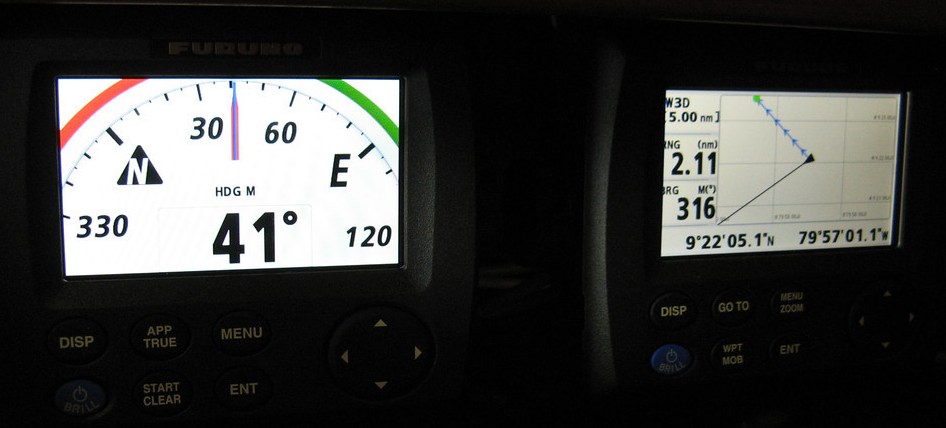
Heading and GPS inputs
Both the Furuno’s Navnet network and the MaxSea programme on the PC allow for multiple heading and position inputs by giving a priority order.
In our case, the heading input comes primarily from the SC30 Satellite Compassand secondly from thePG700 fluxgate compass. A satellite compass gives true heading with no deviation or magnetic variation since it used two or three GPS’s placed inside a radome. The intelligent software can not only give an accurate heading information with an tolerance of 0.5 degrees. It also gives roll and pitch information and can give a heave compensation. In other words the satellite compass does not only know its correct heading, but also its movement forward (pitch), the rolling from side to side and its heaving up and down over the waves with a dozen of centimetres of accuracy. Radar overlay on the plotter, Automatic Radar Plotting Aid (MARPA), autopilot steering and even the discrimination sounder scanning the sea bottom is dead steady and much more accurate. General GPS information is given as a spin-off and the satellite compass acts as our primary GPS.
The PG700 is a very fast fluxgate compass giving its heading information in the NMEA2000 protocol. A fluxgate compass reads the magnetic heading and is thus another source of heading information: The SC-30 uses GPS and the PG700 the magnetic field of the earth. You never know… The magnetic field might malfunction (joke!) or the US military decides to switch off the GPS system (more realistic). Luckily, they don’t control the earth’s magnetic field, yet!
Like most fluxgate compasses, the PG700 automatically adjusts for magnetic variation, as long as the vessel’s position is known. Deviation is automatically calculated by means of a database which is created by turning the boat twice in a circle. Obviously, the SC-30 has neither variation nor deviation and is a perfect means of creating a deviation table for our traditional main magnetic compass on the steering pedestal, which is our third source of heading information.
Rüdiger Engel explains how the various heading sensors and GPS:s work together.Photo by Jessica
While the SC-30 is our first mean of position indication, we have a second GPS calledFuruno GP33. This is a stand alone GPS with its own display. It is fed into the Navnet network as a second GPS and is connected to the VHF and the onboard PC via a traditional, very robust NMEA183 protocol. Should the Navnet network fail, we would still have a position via a serial cable for emergency transmission (VHF) and for a position on the PC (MaxSea). Last, but not least, the GP33 gives the position on its own display, which can be plotted on a paper chart. The GP33 will also be used as the anchor watch since no other instrument needs to be switched on.
As a third means of position indication, we have a GPS built into the FA-50 AIS, which is also fed into the Navnet network.
To sum up, we have three means of heading information of which one is the traditional ship’s compass, and three means of position information, all fed into the network in various protocols and cables.
Basic instruments
 The basic instruments is the log, the depth sounder and the wind instrument. The inputs are given by means of the regatta wind sensor FI-5001L with an extra long shaft so it is not being hidden in lee behind the mast. The speed and depth is given by the Triducer acting as a depth-sounder and giving both speed and water temperature with only one hole in the boat.
A special kind of depth sounder is the additional Bottom Discrimination Sounder BBDS1. This sounder scans the bottom and gives an easily understood picture, which is said to be very helpful when anchoring. This is a brand new type of bottom scanner and it will become very interesting to test.
All data is being presented and compiled in the Navnet plotter, the PC, as well as on individual instruments over the companionway: Two FI-504 Multi-instruments, one FI-501 wind instrument and one FI-502 closed hauled wind instrument, all from the FI-50 series.
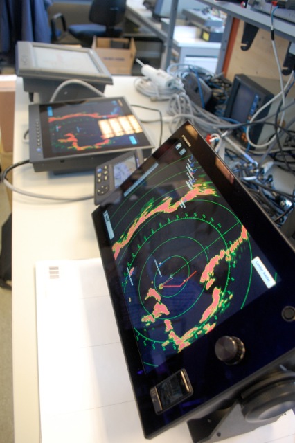
Furuno had set up a network in their lab to demonstrate how the instruments are working together. Photo by Jessica
Slave monitors
The RD-33 slave instrument next to the GP-33 GPS as it will look on Regina Laska
Two RD-33 slave instruments are used to present all available information on the network. One of these is placed at the nav-station, always giving essential information without having to start up the plotter or the PC. The other one is placed in the aft cabin in order to provide full control over the boat while resting off watch. All according to the old saying: “Trust is good – control is better!”
Leon testing the 4-finger scrolling feature yet to be invented
Photo by Jessica
Leon testing the NavNet TZtouch screen in Furuno’s lab. Photo by Jessica
The coolest feature with Furuno’s new Navnet TZtouch is the ability to slave and even monitor literally everything from an iPad or iPhone. The exact picture of the plotter is cloned via the built-in WiFi hob and you can monitor and control everything that is available on the plotter, i.e. the network. This can become a nice teaching tool when undertaking sail training courses when the students can sit in the saloon or in the cockpit with an iPad to follow the navigation, e.g. radar navigation into a tricky channel or archipelago. The old days when 5 heads used to hang over the navigation station trying to see the radar screen is history. And yes, you can sit on the toilet watching where the boat is going!
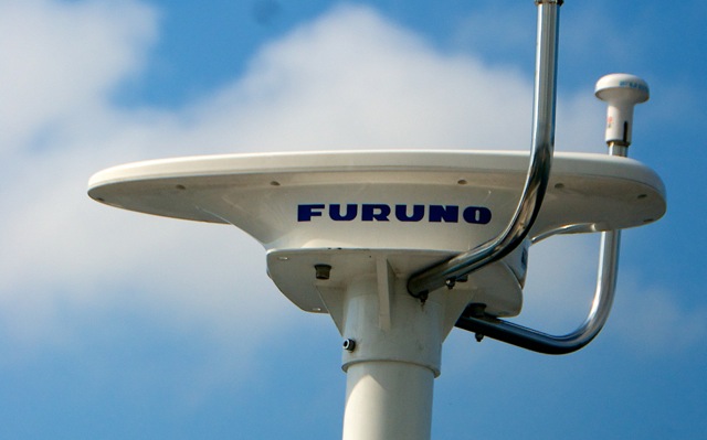
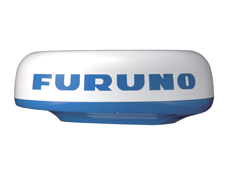 The radar is the 24″ 4 kW NavNet 3D DRS4Dradome radar sensor with a lobe angle of 4 degrees. Yes, I do admit it: I would have loved to have an open array radar. It just looks so cool to have a carousel for the sea gulls on the pole at the back of the boat! It’s macho!
Furuno, however, convinced us that their 4 kW radome antenna has such an intelligent software and gives such an extremely sharp radar picture that I would be able to live with the lobe angle of 4 degrees.
The new black-box radar systems by Furuno have all their electronics built inside the radome, meaning that the radar picture is fed by a standard Ethernet cable into both the plotter as well as the PC. This new feature means that a radar picture can be presented on the PC even if the plotter is switched off, broken or stolen. The simple Ethernet cable to the radar antenna also facilitates disconnecting the radar antenna for winter storage.
Being in the lab:
The radar picture can be seen on the Navnet TZtouch plotter at the outer chart table, the 15″ display at the navstation down below as well as on the iPads onboard.
Photo by Jessica
The discussion became very intense when we talked about the placement of the radar antenna: on the stern pole or on the mast. To me, it has always been a matter of course to have the radar antenna on the pole on aft deck, the so called radar pole. Sails get cluttered around the radome on the mast, I thought, and service becomes more difficult. After all, we have the stern pole already, so why not mount the radar there? My arguments were listened to and then respectfully questioned:
 The main points for having the radar on the mast nevertheless were:
– in swell larger than 2 meters the radar always looks over the waves, even seeing small targets that would otherwise disappear behind the waves
– no ghost echoes resulting from the radar beams reflecting on the boom
– neglectable radiation in the cockpit (an old saying goes that seaman placed themselves in the radar beam in order to make sure that the girls ashore did not get pregnant…)
– no interference between the radar and other equipment with antennas on the stern pole
The reason for not having it on the mast would be the fact that it is more work when demasting for the winter. In some winter storages, the owners are asked to disconnect the radome antennas from the mast, thus avoiding it getting in the way with other masts. On older radar models, disconnecting the cable could also be an issue, whereas modern black-box radars with all the electronics built into the radome, just have an Ethernet cable that is easy to disconnect for the winter.
The discussions become so intense when talking about the placement of the radar antenna, that, in the end, we all stood up by the white board drawing pictures.Photo by Jessica
Another issue could be that targets very close by could be lost with the radar in the mast, but, so they asked, who wants to see things you see with your eyes within a couple of boat lengths anyway? If you can’t see even these, stay in port!
Frank Westphal gestures to demonstrate the importance of a gimballed radar antenna if it is placed at the radar pole, while Rüdiger Engel points at the benefits the radar being placed high above sea level. Photo by Jessica
I admit: the issue with the ghost echos has been quite annoying and with the radar on the mast there would only be a small blind spot exactly behind the boat. If the radar is to be placed on the pole, it needs to be gimbled and placed at considerable height in order to overlook the boom and to minimize radiation onto people in the cockpit.
After the meeting we have been speaking with a lot of experienced people: riggers, sailmakers, equipment suppliers, yards, a former naval radar operator as well as with experienced sailors, including Arne Mårtensson sailing HR62 Yaghan around the world. Arne and Heléne have two of literally everything onboard and therefore one radome Radar in the mast and one on the stern pole and could thus compare both alternatives.
Finally, we have come to the conclusion that it is most sensible to have the radar placed in the mast.
Plotter and PC
On the outer chart table in the cockpit we will install a Navnet TZtouch 14″ plotter. The plotter has a touch screen and its human-machine-interface is similar to an iPad and thus very intuitive. In addition to the touch screen, it still has knobs and buttons so you can control the device even with wet fingers.
At the navstation down below we have the 15″ Furuno multifunctional displayMU150HD. It either acts as a cloned slave-display of the plotter or it acts as a display for the ship’s navigation PC, a 2.5 GHz Mac mini.
Comparing various display options. Photo by Jessica
By means of a software called Parallels we can run MacOS with all its benefits on the Mac as well as Windows 7, both at the same time. In other words: any Windows-software can run “in parallels” with Mac Programs, which means we only need one computer for our software, be it for Mac or Windows.
Our most important Windows-based software is MaxSea Time Zero Explorer with a routing/weather module. This navigation software runs totally independent of the plotter with its own charts. Furuno has prepared for such a redundant system by offering two licenses when buying MapMedia charts from MaxSea: One license for the Navnet TZtouch plotter and another license for a stand-alone PC.
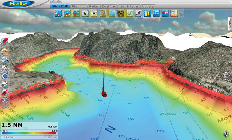
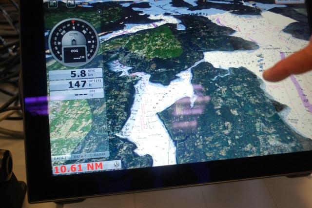
The MaxSea navigation software looks like the virtual reality in a computer game
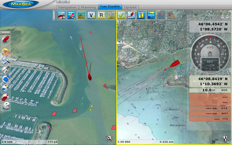
Integrated satellite pictures, 3D panning, AIS-presentation and possible radar overlay is cheating, isn’t it? I will also hold onto teaching classic navigation to my students
The interesting feature with the Time Zero Explorer version is that it fully integrates with Furuno’s equipment in such a way, that the radar can be displayed directly on the PC, turning the radar into a black-box device. In other words, the radar does not needs to go through a plotter, so we have a redundant system even for the radar picture.
Furthermore, the MaxSea program is prepared for two individual GPS-inputs: one from the Navnet Network, i.e. the satellite compass SC-30, and the second one from the stand-alone GP33 GPS via a serial COM-Port (NMEA183). This allows the Mac mini with MaxSea to run with its own charts and an own independent GPS, should the entire rest of the navigation network break down.
Although it sounds very complicated, it is not! All we do is to use one plotter and one PC and make sure that they are able to work independently, creating a redundancy without having to buy two of everything.
Autopilots
The idea of not having to buy two of everything and, instead, building work-arounds, is not really applicable when talking autopilots. Here, we really have to buy two individual autopilot systems, each with an own heading input, a control unit, a course computer and a drive unit. This doesn’t come cheap but is very important for a short-handed crew.
 Autopilot 1
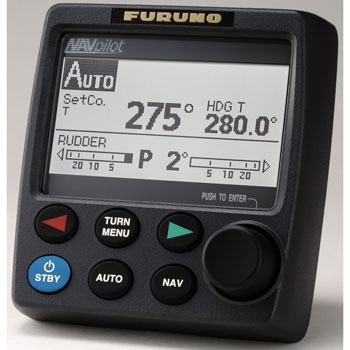
The main autopilot has two displays, one 711on the pedestal (at the helm) and one 711 display over the companionway as a remote control. The reason for having that second display is that we have experienced that we very often sail the boat from under the sprayhood/hard dodger.
The heading information is received from theSC-30 satellite compass, giving an extremely steady heading and course information.
The autopilot 1 then has its own course computer FAP-7002 and will use a Raymarine Type II electrical linear drive directly mounted on the rudder shaft.
Autopilot 2
The second autopilot has one 711 display at the pedestal, the PG700 fluxgate compass (giving magnetic heading inputs) and its own course computer FAP-7002. This autopilot also has its own Raymarine Type II liniar drive.
Both linear drives are mounted on the rudder quadrant and this is the main reason why we choose an electrical/mechanical linear drive rather than a hydraulic drive. The feel at the helm when sailing by hand becomes less sensitive if you have to push two hydraulic cylinders at the same time. With my greatest respect to Furuno, there is no other company who can build an electrical linear drive like Raymarine, who once bought the technology from Autohelm. The old Autohelm design has looked the same for decades and has a fantastic record of positive testimonials. It’s the same type we had on our HR40 Regina and I have hardly heard from anyone with a broken Type II drive. It is quiet, power-efficient and very reliable.
With two drive units readily installed, they can either work individually as described above (one for each autopilot) or, in harsher weather and bigger waves, they can work jointly with one drive pushing and the other one pulling, both getting the input from a single autopilot. What you do is switch them with reverse polarity (one drive gets a plus while the other one gets a minus). Thanks to both drives now working as a team, it reduces wear and prolongs their lives even further.
Communications
 The communication equipment is a huge issue since they do not only cost a lot as hardware but their major cost lies in airtime fees. We do not want to get into the habit of surfing the internet from the open sea and paying 17 USD for each MB! And having a broadband connection without using it is also a bad investment.
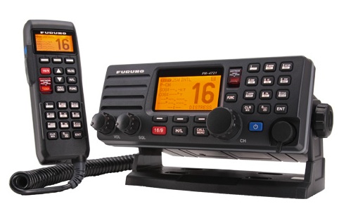
First of all, we will have a FM-4721 VHF with a remote handset and an external loudspeaker in the cockpit.
Secondly, we will keep the SSB that is already onboard: An ICOM802 with its Pactor Modem for E-mails that Laska came with (actually the only electronics we will save from Laska). We will, however, move the antenna tuner for the SSB closer to the backstay and install a KISS-SSB ground plane.
During the meeting with Furuno, we could not really agree on which satellite system to chose, either Inmarsat-C, Iridium, Iridium Pilot (former Open Port) or Fleet Broadband. More investigations have to be made.
For weather information we will use Navtex and Weatherfax, both received by means of one and the same black-box by Furuno: The Fax30. Important to notice is that the Fax30 needs a ground plane to function well (reception in the MF/HF frequency range). We will thus connect our old copper ground plane for the SSB with the Fax30 (while the SSB receives its new KISS-SSB ground plane mentioned above).
Another means of obtaining weather information is through GRIB-files which are sent via e-mail.
E-mails can be received by means of the SSB and the Pactor modem and a yet to be chosen satellite system. In port and many anchorages, e-mails and surfing the Internet can be done via WiFi, for which we need an external amplifying WiFi antenna, theWiFi Bat by Mailasail, which is connected to the Mac mini via USB. The Mac mini will then distribute the Internet via the built in Internet sharing feature by Apple, so there is a “Regina Laska” WiFi Net available for everyone onboard.
The AIS is the FA-50 class B transponder which transmits and receives AIS-information from vessels within VHF-range.
Antennas
With all this equipment, antennas become an issue. They need to be placed so reception becomes optimal while they do not interfere with each other. Especially the radar beams of 4 kW can become very harmful, both for humans and for other equipment.
Going from top to bottom, we will have the dedicated CX-4 VHF antenna in the mast top. This will give optimal range and the VHF is one of our most important pieces of equipment (therefore we carry 3 sets of VHF onboard with two fixed VHF-antennas).
Also in the mast top, we have the FAME1 dedicated FM-Stereo antenna for optimal reception which will be connected to the onboard stereo system. The distance between the CX-4 and FAME1 antenna is to be approx 70 cm.
On the first spreader we will place the CELmar0-1AIS AIS antenna. This is a stainless steel antenna which can bend, should a halyard or so get interfered with the antenna. The high placement of the AIS-antenna is important for range (also within VHF frequency), which also facilitates tracking on marinetraffic.com.
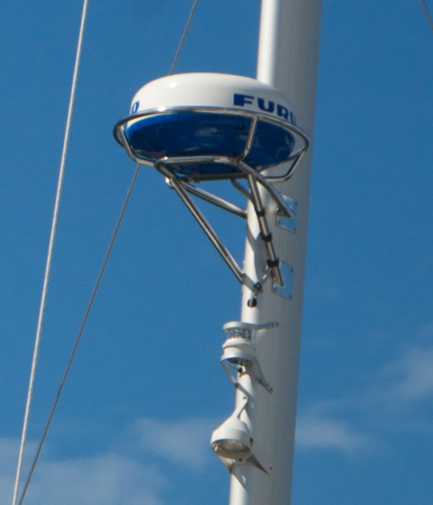
Further down on the mast is the 4 kW DRS4D radar radome antenna.
On the stern of the boat, there is the traditional radar-pole, which has now been renamed to “antenna pole”, hosting the following antennas:
– the SC-30 satellite compass
– the spare CX-4 VHF antenna
– the Fax5 antenna for the Navtex and Weatherfax
– the WiFi-Bat for WiFi reception
– two GPA-017S GPS antennas (for GP-33 and AIS)
– possibly an Iridium antenna